
Pattern Components
Overview
Pattern automates the placement and arrangement of components in Inventor assemblies. You specify how many spaces to add and how far apart each item should be, and the tool applies constraints to position the resulting components precisely.
Patterns can be created directly in the current assembly or placed into a new sub-assembly for better organization and BOM management. You can also choose whether each new item is constrained back to the base component or chained from the previous item, and you can control direction using axes or a custom vector.
How It Works
- Select component(s) to pattern.
- Enter the Spaces count (how many additional instances to create).
- Enter the Distance between instances (single value or 3-part
x:y:z). - Choose Pattern Direction (X/Y/Z/Custom) and optionally Flip.
- Choose pattern behavior options (constrain-to-base, combine, create assembly).
- Confirm to create the pattern and constraints.
Pattern Format
Spaces: Enter any valid Inventor expression that evaluates to a positive integer. This determines how many additional components are added in the pattern.
Distance: Enter any valid Inventor expression that evaluates to a length, or use a three-part expression separated by colons to specify x, y, and z offsets. The three components are evaluated independently and set the offset for each direction, ignoring Pattern Direction.
Distance Expressions
Distance expressions control the spacing and placement of patterned components. There are two main types:
Single Value Distance Expression
A single value expression may contain any valid Inventor input, including functions, parameter names, operators, and units. For example: 2 in + 3 * cos(angle) + max(length1 ; length2).
The expression is assigned to the constraints, not the result value. This means if parameters change, the pattern updates automatically, keeping your design parametric and flexible.
If the pattern direction is along the X axis and the component coordinate system matches the assembly coordinate system, the expression is assigned to the X constraint, and both the Y and Z are set to 0. If the component coordinate system is rotated, the constraint expressions are adjusted to account for the rotation in order to maintain the requested offsets. If the offset direction is not along one of the coordinate system axes and a custom direction is entered, the constraints are again adjusted.
Three Part Distance Expression
A three-part expression sets absolute offsets for x, y, and z. For example: 10 : 20 : 30. Pattern Direction is ignored. Each part can be any valid expression, such as 10 * Offset + 2 in : 20 * Offset + 3 in : 30 * Offset + 4 in.
Note the difference between applying a direction and single offset expression and applying a three part expression. If the direction is 1,1,1 and the offset is 10, the component will be offset equally in the x, y, and z directions and the origin of the component will be 10 units from original. Each of the plane-plane distances will not be 10; these are all less to allow for the absolute distance from origin to origin to be 10 as requested.
The second method is to apply an absolute offset in each direction by supplying a three part coordinate offset. In this case, an offset of 10 : 10 : 10 (direction is ignored) would provide a plane-plane distance of 10 units as requested. However, the distance from origin to origin would be 17.3 - the square root of (10^2+10^2+10^2).
If you use a three-part expression, the pattern direction is ignored and constraints are set for each axis independently. This allows for precise control over the placement of each component in three-dimensional space.
Example Patterns
24
32mm + 5in
2'-11 3/4" + 36in
cos(angle) : sin(angle) : 0
max(length1 ; length2)
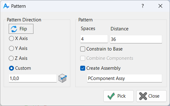
In the clip below, a pattern is created with 4 spaces at 36, 45 degrees off the xz plane (1x, 1y, 0z).
Pattern Direction
Pattern direction values are ignored when the distance value is a three-part input for x, y, and z offsets. For single value distances, the direction determines which axis or custom vector the pattern follows.
Flip reverses the direction of the pattern.
X, Y, Z Axis: Select the axis for pattern direction.
Custom: You may click the pick button to select an edge for pattern direction, or enter a three-number coordinate for the direction.
If you use a three-part distance expression, the pattern direction is ignored and constraints are set for each axis independently. For single value expressions, the direction is critical for correct placement.
Pattern Options
Spaces: Number of spaces to pattern (number of additional items).
Distance: Distance between each component.
Constrain to Base: Constrain all additional components to the first component, ensuring consistent alignment.
Combine Components: When multiple components are selected, this option allows you to combine them into a single demoted assembly prior to patterning (useful for keeping related items together). The demoted assembly uses the default "standard" template in the Inventor templates folder.
Create Assembly: Generate the pattern in a new sub-assembly using the provided name (can be edited later). The assembly uses the default "standard" template in the Inventor templates folder.
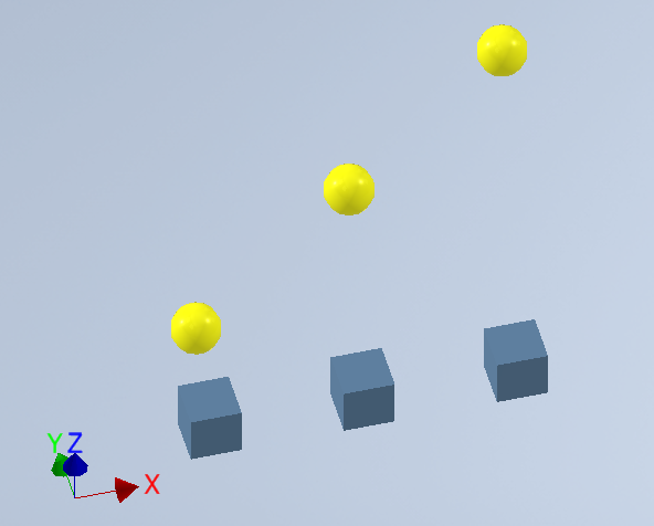
In the example below, the cube was patterned 2 spaces at 30, while the sphere was patterned 2 spaces at 30:0:30 (30 right, 0 back, 30 up).
30 to the right, 0 back, and 30 up.
Dialog Box Input
Spaces: Enter the number of spaces to pattern (integer or valid Inventor expression).
Distance: Enter the distance between components (single value or three-part expression).
Pattern Direction: Select X, Y, Z axis or enter a custom direction.
Flip: Reverse the pattern direction.
Constrain to Base: Constrain all additional components to the first component.
Combine Components: Combine selected components before patterning.
Create Assembly: Generate the pattern in a new sub-assembly.