Overlay Component
Overview
The Overlay tool is used to move, copy, and align a component repeatedly onto selected target components in your assembly. It lets you place an overlay component—such as a duct support, pipe hanger, or bus duct hanger—onto many base components with options to create new occurrences, update parameters, leave constraints free, and control how each placement behaves. This makes it ideal for applying the same support or attachment across an entire system with speed and consistency.
The tool positions and orients the overlay component according to your settings, with options for axis alignment, parameter assignment, offsets, and rotation. You can choose whether to reuse an existing component or generate new ones, and whether to drive parameters from the base component or from the overlay definition. All input is validated before placement, and any issues are reported in a clear error dialog so you can correct them before continuing.
How It Works
- Choose a profile (or create one) to load commonly used settings.
- Select the overlay source (by file or by existing component occurrence).
- Define placement behavior (alignment, upright axis, offsets, rotations, and constrained axes).
- Define parameter behavior (copy parameters and/or parameter expressions).
- Click Pick and select base components to place overlays onto.
- Overlay creates occurrences and applies constraints/parameter updates for each base selection.
Overlay Profiles
Profile List
Profiles store all dialog box control values, allowing quick reuse for common overlay types (e.g., Duct Stand, Duct Hanger Round, Duct Door). You can add or delete profiles, but the default profile cannot be removed.
- Add Profile: Click the plus button to create a new profile using the current settings.
- Select Profile: Click a profile in the list to instantly load its settings.
- Delete Profile: Click the minus button to remove the selected profile (the default profile cannot be deleted).
Overlay Source
Overlay File and Component
Click the File button to select the file to overlay onto the base components. An occurrence of the overlay file will be placed and constrained to the origin of each base component selected.
Click the Component button to select a component in the assembly to overlay onto the base components. An occurrence of the overlay component will be placed and constrained to the origin of each base component selected.
Create New Overlay
Check Create New Overlay to create a new copy of the overlay component each time it is placed on a base component. This is useful if each base component requires a unique overlay (e.g., different sizes).
Only when parameters change
Enter a comma-separated list of parameter names. A new overlay is created only when any of these parameters change in the base component. If another overlay exists with matching parameter values, it is reused.
Overlay Component Position
Align to Base Axes
When checked, the overlay’s X/Y/Z axes align with the base component’s axes. When unchecked, the overlay aligns with the assembly’s global coordinate system.
Maintain Upright
Check to keep the overlay component upright with respect to the assembly. Select the upright axis (X, Y, or Z) from the dropdown. This ensures overlays remain consistently oriented even if base components are rotated or mirrored.
Use Base Coordinates Offset
Check to evaluate the offset expressions in the selected base components. If not checked, expressions are evaluated in the assembly containing the base components.
Offset
Enter X, Y, Z offset as three comma-separated expressions. Expressions may contain parameters, functions, and arithmetic operators. Leave blank for no offset.
Additional Rotation
Enter X, Y, Z rotation angles (in degrees or expressions) for extra rotation of the overlay. This allows for final orientation adjustments after placement.
Axis Constraints
Choose which axes direction (X, Y, Z) to constrain between the overlay and base component. Leaving one axis unconstrained allows you to manually drag the overlay along that axis for fine-tuning. For example, leaving an axis unconstrained lets you slide a duct support along the duct’s length.
Note: Constraints will only apply if the overlay is properly aligned with the base component. If the base is rotated and the overlay is not set to align, constraints will not be created.
Parameter Selection and Assignment
Popout Parameter Menus
Right-click or use the context menu on parameter text boxes to select parameters from a filtered list. Only parameters matching the required type (length, angle, etc.) are shown for each control, making selection fast and error-free.
Copy Parameters
Select parameters to copy from the base component to the overlay. Click the popout menu button to select multiple parameters. Only parameters of the correct type are shown for each control, reducing errors.
Parameter Expressions
You can assign multiple expressions to overlay parameters in the Parameter Expressions text box. Enter one or more assignments, separated by commas. Each assignment should be in the form Parameter = Expression. For example: Width = DuctWidth, Height = DuctHeight + 2. Each expression is evaluated in the context of the base component.
Tip: This is a powerful way to set parameter values for groups of components. For example, DuctStandHeight=60 will assign a value of 60 to all duct stands overlaid onto a duct. When the duct elevation changes, you can update the value accordingly for all overlays.
If the parameter does not exist in the Overlay File or the expression does not result in a valid value, nothing is done.
Workflow
- Select or create a profile for your overlay scenario.
- Choose the overlay file and set up parameters, offsets, constraints, and expressions as needed.
- Click Pick and select base components in your assembly to apply the overlay.
- Switch profiles at any time to quickly change overlay settings for different parts or use cases.
Tips and Troubleshooting
- If the overlay file is missing or not in the workspace, you will be prompted to select a valid file.
- Expressions must be valid and reference existing parameters; errors will be shown if evaluation fails.
- All input is validated before overlay placement. If any issues are found, a comprehensive list of problems is shown for correction.
- The default profile cannot be deleted and is always available as a fallback.
Selecting Base Components
When you click the Pick button, an overlay component is placed and constrained to each base component you select, using your provided offsets, constraints, and parameter settings. If constraints cannot be applied due to misalignment, you will be notified.
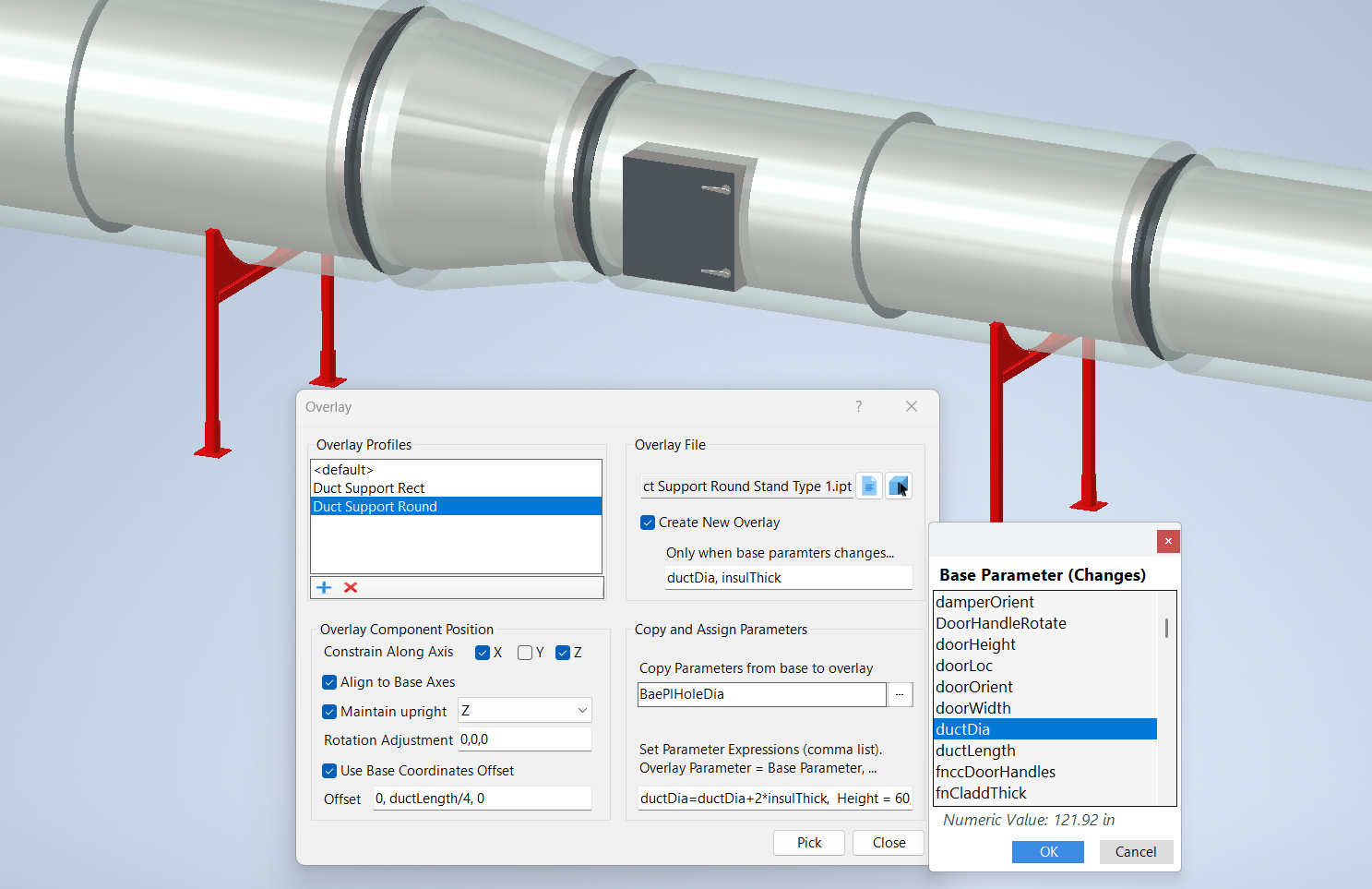
Example
In the example below, a duct support stand is selected as the overlay and the duct fitting was selected as the base component. Each time a duct fitting is selected, a duct stand component is placed, which is a new component if the parameters ductDia or insulThick in the base have changed since the previous placement.
Duct stands are aligned to the duct fittings, remain upright aligned to the assembly Z axis with no additional rotation, and are located a quarter of the duct length from the end.
The duct stand has a parameter named ductDia but does not have a parameter for the insulation thickness. In this case we want a new component when either parameter changes in the base. We don't need to select anything for copy parameter because we make a parameter assignment which assigns ductDia + 2*insulThick to the overlay stand parameter ductDia.
If the duct stand had both ductDia and insulThick parameters, we could eliminate the parameter assignment expression and select both of the parameters as Copy Parameters.
To the right of the Overlay dialog box is a pop‑out parameter list used for selecting parameters for the “Only when base parameters change…” option. With the cursor in the text box, right‑click to choose a base component from which to gather parameters. The parameter list box will then be displayed. Double‑click a parameter, or select it and click OK, to paste the parameter name into the text box.